This topic describes the parameters accessed from the I/Q Out block. These settings allow you to configure the I/Q outputs of the instrument.
I/Q Output controls as based on the optional configuration of the instrument.
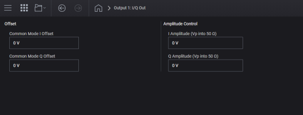
For M9484C, Option AN1 is required. For multi-channel instruments, Option AN1 is available on Channel 1 only. For instruments with Option AN1 and without Option DIQ, the controls available are shown below:
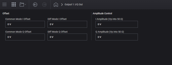
For M9484C, instruments with Options AN1 and DIQ, the controls available are shown below:
This option is used to specify the common mode offset voltage routed to the external I+/- output ports. The Common Mode Offset Voltage raises or lowers the voltage of the signal applied to the I+/- output ports by the same value. A positive Common Mode Offset Voltage raises the voltage of the signal applied to external I+/I- output port above the baseline values, while a negative Common Mode Offset Voltage lowers the voltage of the signal applied to external I+/I- output port above the baseline values. For example, if the Common Mode Offset Voltage is 0.03 volts, both the external I+/I- outputs will be at 0.03 volts (when the output voltages are at their baseline voltage).
The actual output voltage of an individual instrument may clip prior to achieving the minimum or maximum limit value. Verify your instrument is able to achieve your expected output prior to establishing your measurement procedure.
|
GUI Location |
I/Q Out > Common Mode I Offset |
|
SCPI Command |
[:SOURce]:IQOut<channel>:IQADjustment:EXTernal:IOFFset <voltage> [:SOURce]:IQOut<channel>:IQADjustment:EXTernal:IOFFset? |
|
SCPI Example |
IQO:IQAD:EXT:IOFF 5 mV IQO:IQAD:EXT:IOFF? |
|
Preset |
0 V |
|
State Saved |
Yes |
|
Min |
-1.5 V |
|
Max |
1.5 V |
|
Resolution |
0.5 mV |
|
Initial S/W Revision |
A.01.00 |
|
Modified S/W Revision |
A.10.00 A.11.50 updated for M9484C |
|
History |
Min & Max range extended from -/+ 200 mV at A.10.00 |
This option is used to specify the common mode offset voltage signal routed to the external Q+/- output ports. The Common Mode Offset Voltage raises or lowers the voltage of a signal applied to the Q+/- output ports by the same value. A positive Common Mode Offset Voltage raises the voltage of the signal applied to external Q+/Q- output port above the baseline values, while a negative Common Mode Offset Voltage lowers the voltage of the signal applied to external Q+/Q- output port above the baseline values. For example, if the Common Mode Offset Voltage is 0.03 volts, both the external Q+/Q- outputs will be at 0.03 volts ( when the output voltages are at their baseline voltage).
The actual output voltage of an individual instrument may clip prior to achieving the minimum or maximum limit value. Verify your instrument is able to achieve your expected output prior to establishing your measurement procedure.
|
GUI Location |
I/Q Out > Common Mode Q Offset |
|
SCPI Command |
[:SOURce]:IQOut<channel>:IQADjustment:EXTernal:QOFFset <voltage> [:SOURce]:IQOut<channel>:IQADjustment:EXTernal:QOFFset? |
|
SCPI Example |
IQO:IQAD:EXT:QOFF 5 mV IQO:IQAD:EXT:QOFF? |
|
Preset |
0 V |
|
State Saved |
Yes |
|
Min |
-1.5 V |
|
Max |
1.5 V |
|
Resolution |
0.5 mV |
|
Initial S/W Revision |
A.01.00 |
|
Modified S/W Revision |
A.10.00 A.11.50 updated for M9484C |
|
History |
Min & Max range extended from -/+ 200 mV at A.10.00 |
Differential I output requires Option DIQ.
Specifies a differential offset voltage for an in-phase (I) signal routed to the I+/- output ports.
This option is used to specify the total differential offset voltage routed to the external I output port. The Offset Voltage offsets the signal routed to the external I output port by the value of this voltage. This is accomplished by adding half of the Offset Voltage to the signal applied to the external I+ output port and subtracting half of the Offset Voltage from the signal applied to the external I- output port. For example, if the desired I Offset Voltage is 0.05 volts, then 0.025 volts is added to the signal applied to the external I+ output port while 0.025 volts is subtracted from the signal applied to the external I- output port.
|
GUI Location |
I/Q Out > Diff Mode I Offset |
|
SCPI Command |
[:SOURce]:IQOut<channel>:IQADjustment:EXTernal:DIOFfset <voltage> [:SOURce]:IQOut<channel>:IQADjustment:EXTernal:DIOFfset? |
|
SCPI Example |
IQO:IQAD:EXT:DIOF 5 mV IQO:IQAD:EXT:DIOF? |
|
Notes |
If Option DIQ is not installed, an error occurs: 703 Feature not supported; Option DIQ not installed. |
|
Preset |
0 V |
|
State Saved |
Yes |
|
Min |
-3 V |
|
Max |
3 V |
|
Resolution |
0.5 mV |
|
Initial S/W Revision |
A.01.00 |
|
Modified S/W Revision |
A.11.50 updated for M9484C |
Differential Q output requires Option DIQ.
Specifies a differential offset voltage for a quadrature-phase (Q) signal routed to the Q+/- output ports.
This option is used to specify the total differential offset voltage routed to the external Q output port. The Offset Voltage offsets the signal routed to the external Q output port by the value of this voltage. This is accomplished by adding half of the Offset Voltage to the signal applied to the external Q+ output port and subtracting half of the Offset Voltage from the signal applied to the external Q- output port. For example, if the desired Q Offset Voltage is 0.05 volts, then 0.025 volts is added to the signal applied to the external Q+ output port and 0.025 volts is subtracted from the signal applied to the external Q- output port.
|
GUI Location |
I/Q Out > Diff Mode Q Offset |
|
SCPI Command |
[:SOURce]:IQOut<channel>:IQADjustment:EXTernal:DQOFfset <voltage> [:SOURce]:IQOut<channel>:IQADjustment:EXTernal:DQOFfset? |
|
SCPI Example |
IQO:IQAD:EXT:DQOF 5 mV IQO:IQAD:EXT:DQOF? |
|
Notes |
If Option DIQ is not installed, an error occurs: 703 Feature not supported; Option DIQ not installed. |
|
Preset |
0 V |
|
State Saved |
Yes |
|
Min |
-3 V |
|
Max |
3 V |
|
Resolution |
0.5 mV |
|
Initial S/W Revision |
A.01.00 |
|
Modified S/W Revision |
A.11.50 updated for M9484C |
The I/I+ and Q/Q+ output voltage can be adjusted when RF output is not being I/Q modulated, thus CW on the RF output.
For M9484C the I/I+ and Q/Q+ output voltage can be adjusted while continuing to provide modulated RF output.
Option DIQ only.
For use cases where you need to drive higher voltages on the I and Q outputs, and you are not modulating the RF output from the internal baseband, you can enable the Amplitude Control. When Amplitude Control is enabled, use the I and Q Output Amplitude settings to adjust the output voltages. When Amplitude Control is enabled, the RF output will be CW.
|
SCPI Command |
[:SOURce]:IQOut<channel>:IQADjustment:EXTernal:AMPLitude[:STATe] ON|OFF|1|0 [:SOURce]:IQOut<channel>:IQADjustment:EXTernal:AMPLitude[:STATe]? |
|
SCPI Example |
IQO:IQAD:EXT:AMPL ON IQO:IQAD:EXT:AMPL? |
|
Notes |
State is ON and not changeable, attempting to set to OFF raises error "703, Feature not supported; Amplitude Control State is always on for this instrument." |
|
Preset |
ON |
|
State Saved |
Yes |
|
Initial S/W Revision |
A.07.00 |
|
Modified S/W Revision |
A.11.50 updated for M9484C |
Option DIQ only.
Sets the maximum voltage on I+ and I-. Maximum voltage occurs when waveform I data is 16-bit integer maximum (+32767), with minimum voltage occurring when I data is -32768. The voltage is for I into a 50 Ohm load.
|
SCPI Command |
[:SOURce]:IQOut<channel>:IQADjustment:EXTernal:AMPLitude:I <voltage> [:SOURce]:IQOut<channel>:IQADjustment:EXTernal:AMPLitude:I? |
|
SCPI Example |
IQO:IQAD:EXT:AMPL:I 1V IQO:IQAD:EXT:AMPL:I? |
|
Preset |
0 |
|
State Saved |
Yes |
|
Min |
0 |
|
Max |
0.95 Vpeak |
|
Resolution |
0.001 |
|
Initial S/W Revision |
A.07.00 |
|
Modified S/W Revision |
A.11.50 updated for M9484C |
Option DIQ only.
Sets the maximum voltage on Q+ and Q-. Maximum voltage occurs when waveform Q data is 16-bit integer maximum (+32767), with minimum voltage occurring when Q data is -32768. The voltage is for Q into a 50 Ohm load.
|
SCPI Command |
[:SOURce]:IQOut<channel>:IQADjustment:EXTernal:AMPLitude:Q <voltage> [:SOURce]:IQOut<channel>:IQADjustment:EXTernal:AMPLitude:Q? |
|
SCPI Example |
IQO:IQAD:EXT:AMPL:Q 1V IQO:IQAD:EXT:AMPL:Q? |
|
Preset |
0 |
|
State Saved |
Yes |
|
Min |
0 |
|
Max |
0.95 Vpeak |
|
Resolution |
0.001 |
|
Initial S/W Revision |
A.07.00 |
|
Modified S/W Revision |
A.11.50 updated for M9484C |